MOJ S.A.
Tokarska 6 Street, 40-859 Katowice
T: +48 (32) 604 09 00
F: +48 (32) 604 09 01
E: sekretariat@moj.com.pl
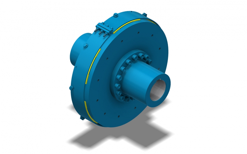
The primary application of the flexible detachable couplings of the SPIN type is to connect the electric or hydraulic drive motor to the shaft of the driven equipment. They are recommended wherever it is difficult to disassemble the motor.


A Type "U“ insert can be replaced without disassembling the engine from the drive system. Type SPIN couplings should not be used in drive systems with very large dynamic torque changes due to their simple construction (only the elastic element of Type 'U' is used).
SPIN type couplings tolerate angular misalignment between the motor shafts and the driven equipment well but require more precise radial alignment. They can be used in machinery intended for operation in underground mines of methane explosion classes a, b, c, and coal dust explosion classes A and B, provided that machines equipped with these couplings have undergone EC type-examination.
The primary application of elastic SPIN type couplings is to connect an electric or hydraulic drive motor to a shaft of the driven equipment, such as gearboxes in belt and scraper conveyors, compressors, pumps, fans, and other devices. It is recommended to use them in situations where disassembling the motor is difficult. The Type U insert can be replaced without removing the motor from the drive system."
| Couplingtype MOJ (mechanical size) | 4 | 8 | 16 | 32 | 50 | 75 | |
|---|---|---|---|---|---|---|---|
| Transmitted power (1500 rpm) | kW | 55 | 100-132 | 200 | 315 | 500 | 750 |
| Maximum rotational speed | min -1 | 3000 | 3000 | 3000 | 3000 | 1500 | 1500 |
| Rated torque | Nm | 350 | 852 | 1283 | 2020 | 3000 | 4000 |
| Acceleration torque | Nm | 875 | 2129 | 3207 | 5051 | 8000 | 10000 |
|
Angular deformation of the couplingat rated torque |
(°) | ok. 5 | ok. 6 | ok. 6,5 | ok. 7 | ok. 5 | ok. 5 |
| Axial assembly deviation ΔP (for the construction site) |
mm | 1–1,5 | 1–1,5 | 1–1,5 | 1–1,5 | 1–1,5 | 1–1,5 |
| Installation offset, radial offset ΔPr | mm | 1,5 | 1,5 | 1,5 | 1,5 | 1,5 | 1,5 |
|
Permissible inclination angle of the couplinghalves axis |
(°) | 1,5 | 1,5 | 1,5 | 1 | 1 | 1 |