MOJ S.A.
Tokarska 6 Street, 40-859 Katowice
T: +48 (32) 604 09 00
F: +48 (32) 604 09 01
E: sekretariat@moj.com.pl
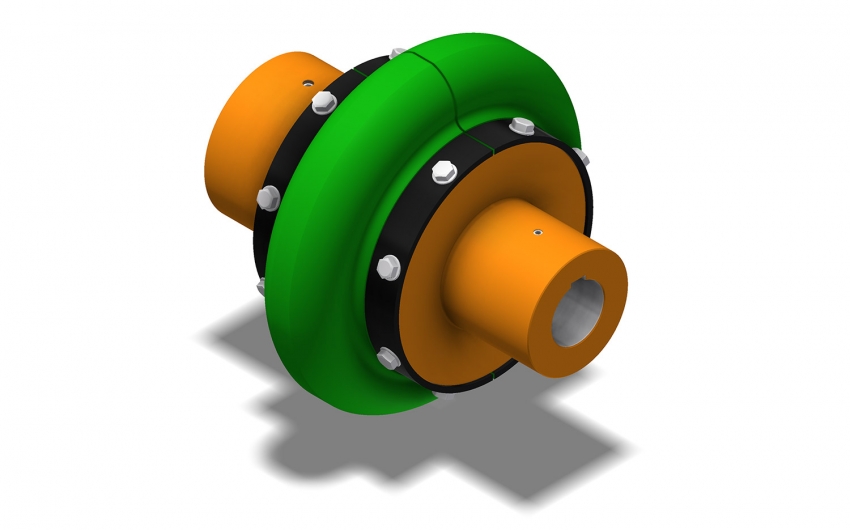
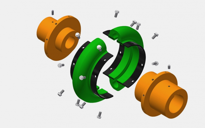
A DUAL-use coupling consists of two hubs and a flexible insert. The forms of the flexible insert ensure optimal interaction even in the case of imprecise alignment between the motor and the driven device shafts.


The high flexibility of the elastomer insert minimizes the axial and radial forces acting on the bearings. Highly elastic couplings with a DUAL insert require no lubrication and are chemically resistant. These couplings are characterized by quick assembly and a low number of spare parts. Couplings with a DUAL insert are used based on the individual characteristics of the drive system and customer needs.
The highly elastic disassembly couplings of the DUAL type are a special design of couplings and, due to their manufacturing technology, can be used in underground mines in methane and coal dust explosion zones. These couplings are used to transmit power from the electric motor to the gearbox of machinery and equipment such as pumps, fans, mixers, belt and roller conveyors, overhead cranes, and more.
Manufactured by MOJ S.A.
| The size of DUAL insert | TKN | TKmax | φN | φmax | nmax | Kr | Ka | Kw | ΦD | ΦAmax | L | S |
|---|---|---|---|---|---|---|---|---|---|---|---|---|
| [Nm] | [Nm] | [°] | [°] | [min-1] | [mm] | [mm] | [°] | [mm] | [mm] | [mm] | [mm] | |
| 002 | 21 | 42 | 5 | 10 | 7500 | 1,6 | 4,7 | 4 | 89 | 20 | 146 | 78 |
| 003 | 41 | 82 | 5 | 10 | 7500 | 1,6 | 4,7 | 4 | 102 | 28 | 184 | 78 |
| 004 | 62 | 124 | 8 | 16 | 7500 | 1,6 | 4,7 | 4 | 116 | 34 | 184 | 78 |
| 005 | 105 | 210 | 8 | 16 | 7500 | 1,6 | 6,3 | 4 | 137 | 42 | 184 | 97 |
| 010 | 164 | 328 | 10 | 20 | 7500 | 1,6 | 6,3 | 4 | 162 | 52 | 184 | 97 |
| 020 | 260 | 520 | 10 | 20 | 6600 | 2,4 | 6,3 | 3 | 184 | 65 | 238 | 108 |
| 030 | 412 | 824 | 9 | 18 | 5800 | 2,4 | 6,3 | 3 | 210 | 80 | 238 | 116 |
| 040 | 622 | 1244 | 9 | 18 | 5000 | 2,4 | 6,3 | 3 | 241 | 100 | 238 | 124 |
| 050 | 864 | 1728 | 6 | 12 | 4200 | 2,4 | 6,3 | 3 | 279 | 130 | 238 | 140 |
| 060 | 1412 | 2824 | 6 | 12 | 3800 | 3,2 | 9,5 | 2 | 318 | 140 | 318 | 160 |
| 070 | 2486 | 4972 | 8 | 16 | 3600 | 3,2 | 9,5 | 2 | 356 | 150 | 318 | 175 |
| 080 | 4463 | 8926 | 10 | 20 | 2000 | 3,2 | 9,5 | 2 | 406 | 170 | 318 | 222 |
| 100 | 9605 | 19210 | 11 | 22 | 1900 | 4,8 | 15 | 1,5 | 533 | 220 | - | 248 |
| 120 | 19211 | 38400 | 10 | 20 | 1800 | 4,8 | 15 | 1,5 | 635 | 300 | - | 294 |
| 140 | 38442 | 76840 | 10 | 20 | 1500 | 4,8 | 15 | 1,5 | 762 | 380 | - | 352 |
TKN - TKN – Rated Torque – a torque that the coupling can continuously transmit within the permissible speed range during normal operation. This torque should exceed the rated torque of the driven device by a value depending on the type of work, rotation, temperature, and expected geometric deviations.
TKmax - Maximum Torque – the maximum value to which the torque load on the couplingcan briefly increase.
φN - The relative angular displacement of the couplinghalves loaded with rated torque.
φmax - The relative angular displacement of the couplinghalves loaded with maximum torque.
nmax - Maximum rotational speed.
Kr - Permissible splitting of the axis of the couplinghalves during continuous operation.
Ka - Permissible elongation or compression of the elastomer insert during continuous operation.
Kw - Permissible shear angle of the axis of the couplinghalves during continuous operation.
ΦD - The outer diameter of the elastomer insert.
ΦAmax - Maximum diameter of the hub hole.
L - Length of the elastomer insert (two variants according to L and S markings).